DESCRIPTION
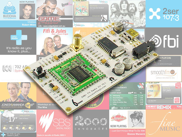
Designed in Australia, the DAB+ FM Digital Radio Development
Board Pro with SlideShow provides a platform for developing and
evaluating DAB+, SlideShow and FM receiver. The board
contains a Keystone T2_L4A_8650C DAB/FM module and a Microchip
PIC18F14K50 microcontroller.
The T2_L4A_8650C module is an ultra
low power DAB/FM receiver module with the following features:
- ETSI EN 300 401 compliant receiver
- DAB/DAB+ sensitivity to -99dBm (typical)
- Decodes multiple audio services up to 256kbps without external
RAM
- FM with RDS (RDS reception is subject to certain condition of
power level and frequency deviation)
- Combined antenna input for FM / Band3
- Support DAB L-band reception (*** Although the Keystone
module supports L-Band, the SMA connector has no connection to
the L-Band pin, customer will need to solder a separate
antenna and other passive components to make it work.)
- Serial control interface
- RoHS compliant
- SlideShow
The Microchip PIC18F14K50 provides a
USB to Serial interface for the T2_L4A_8650C module to communicate
with the host PC. Despite the sample code provided in this
Development Board for communicating with the board is based on
serial communication, user can analyse the serial communication
and implements a driverless HID protocol by rewriting the firmware
on the PIC18F14K50.
Board Dimension
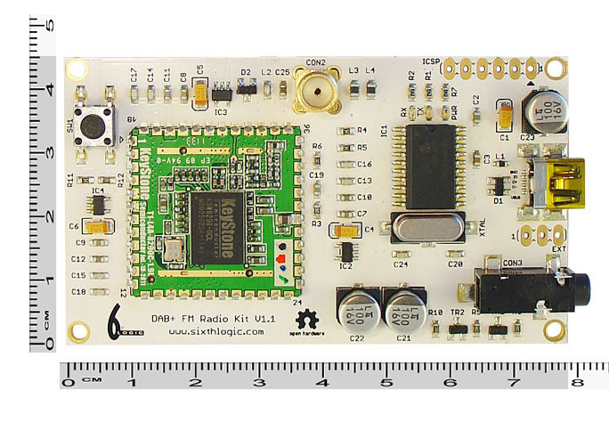
78mm x 45mm
What can you do with it?
- Build a PC controlled DAB+ FM Digital Radio
- Build a CAR PC DAB+ FM Digital Radio
- Build a standalone DAB+ FM Digital Radio (requires external
microcontroller)
New SlideShow Feature
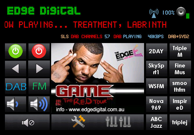
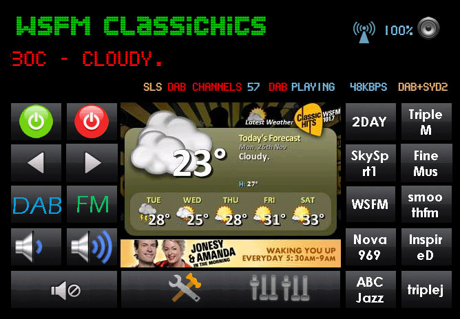
Board will display SlideShow transmitted
from the radio stations. SlideShow including
weather, news, album cover, race odds, etc.
Feature Summary
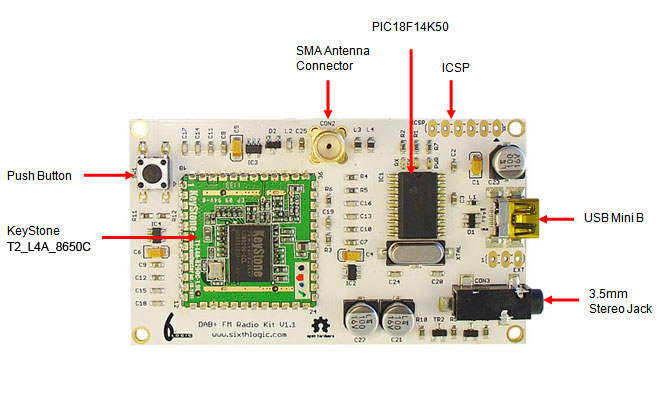
- KeyStone T2_L4A_8650C DAB/DAB+/FM radio module
- Microchip PIC18F14K50 USB Flash Microcontroller
- 12 Mhz crystal
- standard ICSP programming port for programming the PIC18F14K50
- EXT port logic signal for controlling external audio chip
power and mute
- status LED, RX (orange) and TX (green)
- power LED (red)
- Bootloader push button
- 1.2VDC, 1.8VDC, 3.3VDC LDO
- 3.5mm stereo jack
- SMA antenna connector
- Dimensions : 78mm x 45mm
HARDWARE DESCRIPTIONS
Power Supply Circuit
The board is typically powered by
5VDC from USB. The PIC18F14K50 is drawing power directly
from the USB. From the USB’s 5VDC, the power is further
distributed into 1.2VDC, 1.8VDC and 3.3VDC LDO to the KeyStone
T2_L4A_8650C module. The power of these three LDO is controlled by
the SHDN pin.
Microchip PIC18F14K50
This microcontroller is used to
provide a Virtual Serial Port to the KeyStone module. It is
flashed with a customised CDC RS-232 Emulation Demo
firmware. Other than performing the standard serial
emulation, it also control the power, reset and audio shunt of the
KeyStone module.
Reset Circuit
Reset of the module is performed by
RESET pin emulated by DTR of the virtual serial port.
ICSP
The ICSP programming port is the
standard Microchip’s In-Circuit Serial Programming port and is
compatible with Microchip’s PICkit.
EXT
EXT port has two 5V logic signals,
¯SHDN and ¯SHNT. They are used to control external
audio circuitry’s power and mute.
Push Button (SW1)
This button, when pressed during a
power-up, will trigger the PIC18F14K50’s USB HID bootloader in
programming mode.
Demo Software
Links
DOWNLOAD